Did some studying of the service manual today. Carried on with the investigation of the 5v rail. Rather than try to explain with the service manual I thought I'd draw a connectivity diagram. Its not complete but it does identify key components that would benefit from independent regulation. If you want the manual, you can download it HERE.
By identifying the components in the digital signal path, you can find out how they are powered and therefore which psu components can be changed and consider what you might change them to. By using a block diagram approach to the digital signal path through the player we list the devices in the chain prior to the analogue output.
HF -> Decoder and RAM -> oversampling filter and SPDIF encoder -> DAC
At the DAC the analogue signal is created before going to the audio output stage which runs from the +&-15v rails
With respect to the DAC chip SAA7350, the datasheet for the chip confirms 5 separate supply pins. Digital, Analogue Timing Left, Analogue Timing Right, Analogue Left and Analogue Right. Looking at the service manual, each of these pins is connected to the common 5v rail via a low value feed resistor. Each supply also has a local 47uF electrolytic decoupling cap along with a surface mount 47nF ceramic under the board.
By doing the same, for each of the interesting chips, we can build a list of supply pins. Most other chips only have 1 supply pin.
Anyway, this is the DAC so you can see what I'm talking about in the manual.

By following the same process for each device we end up with this (which is not complete but 95% there)

The devices including the interesting capacitors are listed here
SAA7350 - DAC
Pin
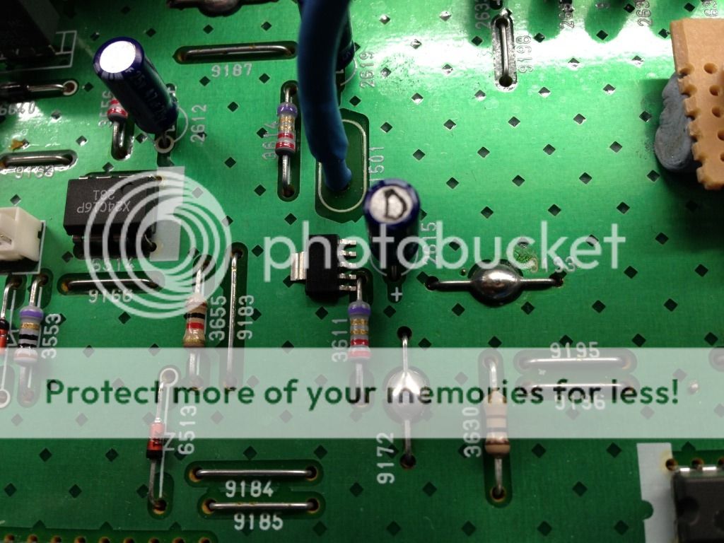
12 VDDD- Via 3611 feed resistor, Cap 2615 - 47uF + 2614 smt 47nF
18 VDDAR- Via 3614 feed resistor, Cap 2619 - 47uF + 2621 smt 47nF
27 VDDATR- Via 3626 feed resistor, Cap 2639 - 47uF + 2641 smt 47nF
29 VDDATL- Via 3625 feed resistor, Cap 2638 - 47uF + 2640 smt 47nF
39 VDDAL- Via 3613 feed resistor, Cap 2618 - 47uF + 2620 smt 47nF
SM5840 - Filter
14 VDD- Via 3646 feed resistor, Cap 2611 - 47uF + 2610 smt 47nF
SAA7310 - Decoder
28- Via 3602 feed resistor, Cap 2604 - 33uF + 2603 smt 22nF
MN4262-15 - RAM (for decoder)
9- Via 3601 feed resistor, Cap 2602 - 33uF + 2601 smt 22nF
We also need to do the same for the main CPU and the SPDIF driver chip (if we are keeping it). The remainder can potentially run from the original shared 5v reg.
Now we have identified each supply pin, we can look to regulate separately

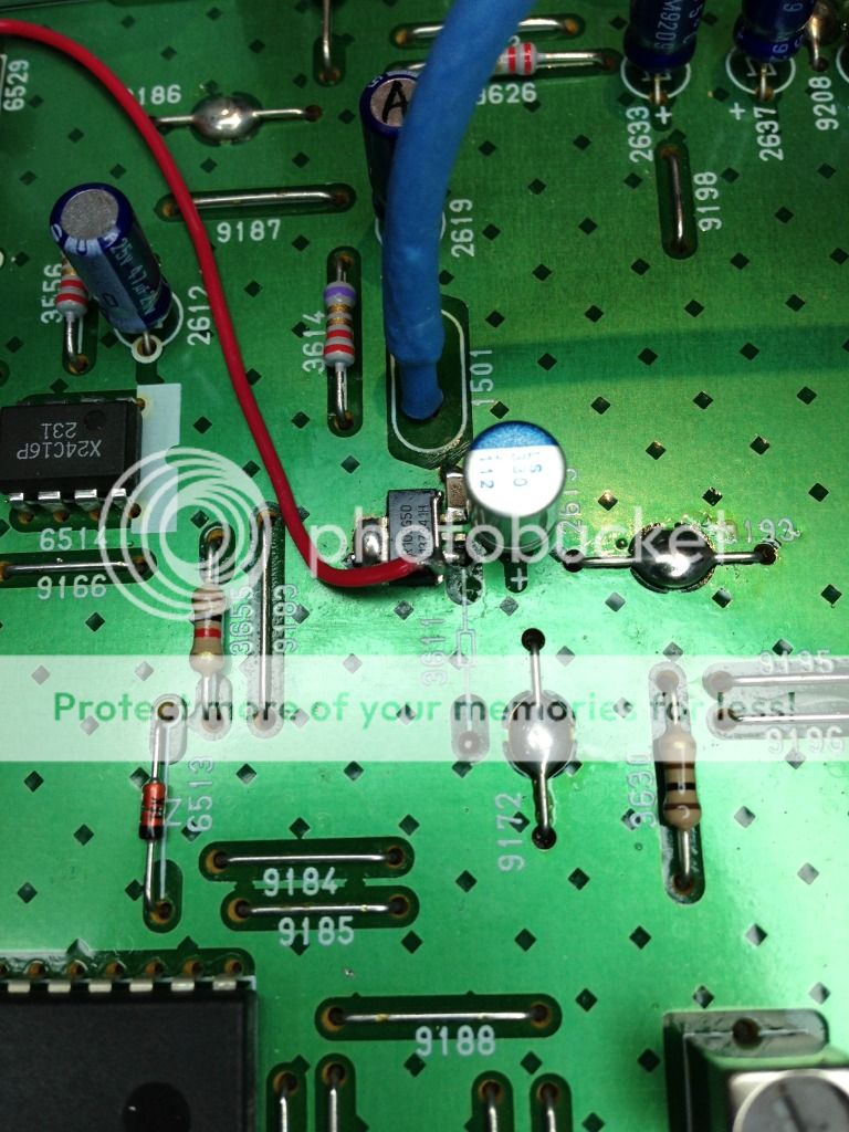
****** do not just copy this last image as the reg in the picture will fail when used with a supply voltage greater than 10 volts!!!!
I'll explain more tomorrow